Precisometer, based at CometLab in the Netherlands, needed a stage that moves a microscope sample by a few micrometres, built for under €20. After nine FFF-printed designs, the open-source Arkin Project shows what printed mechanics can do in precision motion, where they stop, and why the printer was rarely the problem.
A commercial motorised precision stage can easily cost more than €1,000. That was too much for the Arkin Project, which is developing low-cost, open-source optical tweezers for teaching labs and citizen scientists. Optical tweezers use a tightly focused laser beam to hold microscopic particles, in Arkin’s case beads about 4 µm across. The trap only works if the sample stays still. If the stage drifts by a few micrometres, the bead escapes.
The team therefore set out to build a sample stage from FFF-printed parts and inexpensive har.dware. The designs, assembly guides, firmware and measurements are published on GitLab, including the versions that did not work.
Print the shape, buy the precision
The stages use a hybrid approach. The printed parts set the geometry. Standard metal parts provide the surfaces that roll, slide and carry load.
All structural parts are designed for an ordinary FFF printer with a 0.4 mm nozzle, printed in PLA. The project’s design rules call for no special tools beyond hand tools and a printer, and for print times of no more than about four hours per part.
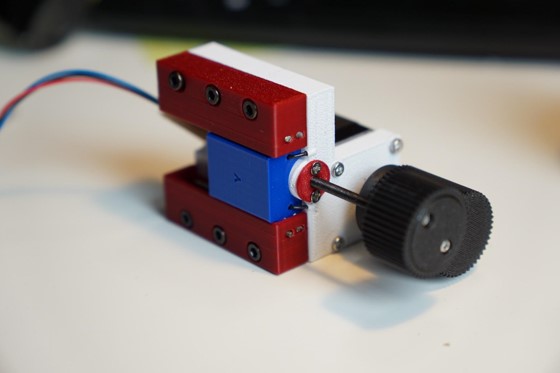
In the latest design, the printed parts of one axis are the base, the carriage, two rail blocks, a ball spacer, a nut spacer and cap, and the two drive gears. Together they use about €1–2 of filament. The carriage never slides on plastic. It runs on 2 mm stainless-steel rods and two rows of five 3 mm steel balls, and the printed parts only hold that metal in place. A standard M3 screw serves as the lead screw and runs through two brass nuts.
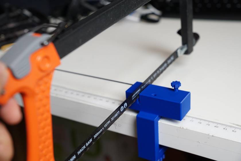
Printing also supplies the tools: a printed jig holds the 2 mm steel rod at a fixed length while it is cut with a hand saw. Image: Arkin Project / Ali Azadbakht.
The printer also makes the tools. A printed cutting jig, now in its third version, lets builders cut the steel rods to repeatable lengths with a hand saw. Support material has to be cleaned completely out of the rod channels and ball tracks, because any residue adds friction. Because printers differ, the editable Fusion 360 and STEP files let builders adjust clearances for their own machine. Elsewhere in the project, some printed adapters are supplied in several fit tolerances for the same reason.
Eight versions with a €1 motor
The first design path used the 28BYJ-48, a small geared stepper motor that costs about one euro. Over eight versions, the design gained printed rails, steel rods and balls, spring preload, separate Z-axis designs with microscope objective holders, and finally, in version 8, a printed flexure. This compliant platform under the lead-screw nut was meant to stop a misaligned screw from pushing the carriage sideways.
The stage still wobbled. Video tests showed why. The motor’s internal gearbox has backlash, and its output shaft can move sideways and in and out. The flexible coupling between motor and screw bends and twists, so the screw does not turn around one clean axis. Tolerances also add up across eight rods and ten balls. Tightening the rails removes play but makes the small motor stall; loosening them lets the carriage rock.
The flexure did not remove the runout. It only moved the error somewhere else.
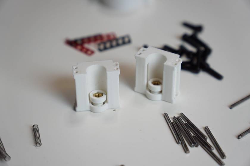
Version 8 of the 28BYJ-48 design: the brass M3 nuts sit on printed flexures intended to stop screw misalignment from reaching the carriage. Image: Arkin Project / Ali Azadbakht.
Version nine: printed gears instead of a direct coupling
The second design path drops the cheap motor. A NEMA 11 stepper motor drives the M3 screw through a printed 1:1 gear pair, so the screw turns on its own fixed axis and the flexible coupling disappears. The screw passes through two aligned brass nuts with a printed spacer between them, which supports it at two points and reduces thread play. Elastic jewellery cord pulls the carriage against the drive, so the remaining clearance is always taken up in the same direction.
The visible rocking disappeared. This was not because the printer had become more accurate, but because the drive no longer passed shaft error into the carriage.
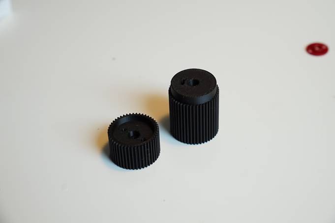
The printed 1:1 gear pair that replaced the flexible coupling between motor and lead screw. Image: Arkin Project / Ali Azadbakht.
The mechanical parts for one axis cost about €10–17, including the motor. With a TMC2209 driver and an Arduino UNO R4 Minima, a complete first axis costs about €25–40. Two modules mounted at right angles form an XY stage.
What the measurements show
On paper, the stage is extremely fine. The motor has 200 steps per revolution, the driver divides each step into 256 microsteps, and the screw advances 0.5 mm per revolution. That works out at 9.77 nm per microstep. In practice, printed plastic and an M3 thread cannot follow steps that small.
To find the real limits, the project measured one NEMA 11 axis optically. The stage has no position sensor, so a USB microscope tracked a feature on the carriage while the stage moved in both directions, in steps from 1 to 8,192 microsteps, eight times per step size. A webcam followed the longer moves.
- Smallest useful move: about 2.5–4 µm. Below that, the printed body and the M3 thread flex, store the motion and release it irregularly.
- Between 5 and 80 µm, the response is linear (R² = 0.978) and repeatable to about 0.5–2.7 µm (standard deviation). However, the carriage moves much less than commanded: an 80 µm command produced about 13 µm of movement. The stage therefore has to be calibrated.
- Over millimetre distances, mounting and rail seating dominate. Straightness was 65 µm RMS over 1.57 mm of travel, and returning to the starting position left an error of about 110–171 µm.
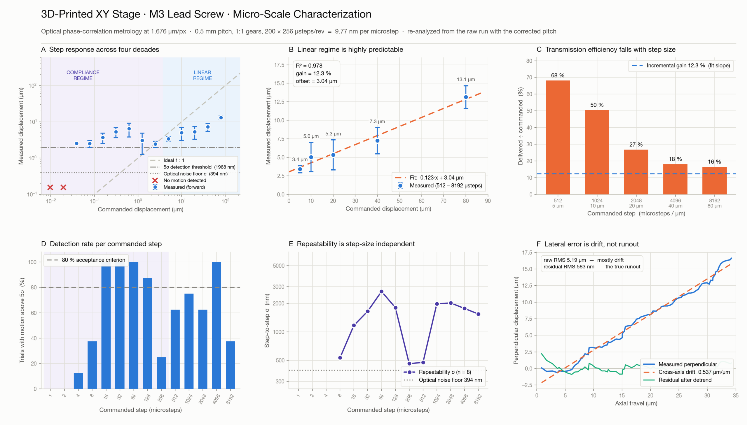
Fine-motion measurements on the NEMA 11 axis: commanded versus measured movement, repeatability and sideways drift. Source: Arkin Project. Click on the graphic to enlarge
The conclusion is modest but useful. A printed stage with metal bearing surfaces and a stiff drive can make repeatable moves of a few micrometres over short distances. Accurate positioning over millimetres needs more: better rail seating, a stiffer mount, independent length calibration and improved screw preload. These are the project’s next steps.
Applications
The stage was built to position samples for Arkin’s optical tweezers, which are based on the open-source OpenFlexure microscope. The same approach suits other situations where micrometre-scale moves are useful but a commercial stage is too expensive, such as positioning samples on low-cost microscopes, aligning optical components, teaching labs and citizen-science projects.
Because every design change is documented with measurements, the stages also work as teaching material. Students can see how the choice of motor, coupling or preload changes the result. The 28BYJ-48 versions remain useful for teaching and coarse positioning, but the project does not recommend them where wobble-free micrometre motion is needed.
Open files
Everything is published under the CERN Open Hardware Licence v2 (strongly reciprocal): STL files, editable Fusion 360 and STEP models, step-by-step assembly guides with photographs, Arduino firmware, raw measurement data and the analysis scripts. The Arkin Project is funded by NLnet through the NGI0 Commons Fund and supported by Precisometer.
Anyone building their own stage can start at version nine.
At a glance: NEMA 11 axis
| Printing | FFF, 0.4 mm nozzle, PLA |
| Metal parts | 2 mm stainless-steel rods, 3 mm steel balls, M3 lead screw (0.5 mm pitch), two brass nuts |
| Drive | NEMA 11 stepper, printed 1:1 gears, TMC2209 driver, Arduino UNO R4 Minima |
| Mechanical cost per axis | about €10–17 |
| Smallest useful move | about 2.5–4 µm |
| Repeatability (5–80 µm moves) | 0.5–2.7 µm (standard deviation) |
| Licence | CERN-OHL-S v2 |
Author: Ali Azadbakht, PhD at Precisometer
Links
- NEMA 11 stage and assembly guide: https://gitlab.com/ali.azadbakht/arkin-project/-/tree/main/Files/XY%20Stage%20Nema%20with%20Gear
- Measurement report, data and scripts: https://gitlab.com/ali.azadbakht/arkin-project/-/tree/main/Files/XY%20Stage%20Nema%20with%20Gear/3D%20Printed%20Stage%20Report
- 28BYJ-48 versions 1–8 and Z designs: https://gitlab.com/ali.azadbakht/arkin-project/-/tree/main/Files/XYZ%20Stage%20with%2028BYJ-48
Precisometer open-source projects: https://www.precisometer.com/open-source